|
|
||
|
|
|
|
|
|
|
|
||
|
|
|||
| |||||||||||||
Rear Brake UpgradeAfter installing my big front brakes, it felt like the rear of the car was just along for the ride during braking. So, I decided to upgrade the rear brakes, too. One option is to get the complete rear brake setup from the Japanese RZ model. The rear rotors increased in diameter from about 11.5" to 12.2" and had the same thickness. The RZ calipers are much like the stock calipers from the U.S. model, except that they accommodate the larger rotor. The caliper has the same piston bore as the U.S. caliper (1.37", I think), mounts to the upright with no modifications, and retains the parking brake operation. This seems like a great upgrade, and they are no doubt the way to go if you install the front brakes from the RZ model, but some reports from the track junkies indicate that you need more rear brake to balance out a larger-than-RZ front brake setup. This makes a lot of sense considering the rear RZ brakes are designed to conservatively complement the front RZ brakes, and my front brakes are beefier than the RZ fronts. Note: Sometimes the bigger brakes from Mazda are referred to as the "RS" brakes. I really don't know if it is the RS or RZ (or perhaps both) that have the bigger brakes. Mazdaspeed Motorsports Development lists them as "RZ" parts, so that is how I refer to them here. I think we are all referring to the same thing -- "bigger RX-7 brakes from Mazda". So, I decided to pursue something larger without breaking the bank. The key to the solution I chose is a set of caliper brackets from Widefoot Racing that allow you to use Wilwood NDL calipers with the RZ rear rotors. The calipers are small 4-piston fixed calipers with 1.12" pistons (as opposed to the floating single piston design of the Mazda parts). The only downsides to this solution are that you have to do a little grinding on the upright and you lose the parking brake functionality. The grinding required turned out to be pretty minor, and it does not preclude you from switching back to the Mazda calipers if you choose to back down on the brakes in the future (to sell the car or whatever). I will miss the parking brake, but I figure I can just put the car in gear and take care not to park on too much of a grade. There is a wheel chock in the stock jack set from Mazda, and I figure I can employ that if I can't find level ground to park on. Unfortunately, the rotary does not provide much resistance to motion even in first gear as I discovered from testing after getting a pointer to this fact from someone reading the mailing list. Oh well, good brakes are worth the hassle. Gathering the PartsHere is a list of all the parts you need to do this brake upgrade, organized by source: Widefoot Racing(Their web site isn't up yet, but I expect it to appear soon)
Mazdaspeed Motorsports Development(note that these aren't "stock" U.S. parts, so you don't need a Team Support account to order the rotors)
Essex Parts Services(Essex has outstanding customer support, knows what you need for this upgrade, and has access to all the pads and brake parts you need. They also had better prices than any source I found while shopping on the internet for the calipers. Call and ask for Scott Refert.)
I decided to get some Ferodo DS2500 pads for the street and DS3000 pads for the track. It seems like it is a good idea to use the same pads front and rear so they will behave similarly as they heat up, so I got some matching sets of pads for street and track. Orchard Supply Hardware (or your local metric-friendly hardware store)
Note: You can deviate from the hardware listed here slightly depending on what is available. These were the best (highest grade) fasteners that I could find so that is what I used. The most important part is finding the M10 x 50mm bolts, as the length is critical to avoid hitting the rotor or having to load up on washers to adjust their protrusion. Auto Parts Store / Race Supply Shop
Here's a picture of all the big parts:
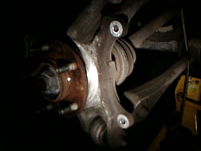
PricingI am sure you are wondering how much this is going to cost. I don't want to quote exact prices because they might change and I don't want to have to update the page all the time. However, if you budget $800-$900 you should be able to get everything you need including one set of rear pads. The price will obviously be higher if you decide to get some more brake pads for the front of the car or for the track. I think this setup is a pretty good deal considering how much brake stuff usually costs. Installation1. Remove the Stock StuffThe first thing you need to do is remove all the stock brake stuff. I left part of the caliper hanging from the hose to avoid losing fluid while I was installing the new caliper. You will also need to remove the rotor backing plate as it won't work with the larger RZ rotor. I think you can get the backing plates for the RZ rotors from Mazdaspeed Motorsports Development, but they are kind of pricey and I don't have front backing plates so I figure it was okay to just remove them. I used some snips to cut in from the outside toward the center and then used some pliers to twist the metal to get it to snap the plate all the way to the center. There are no fasteners and the backing plate is just pressed onto the upright. It is easy to cut and once you tear it down to the center, you can just pull it off. I guess you could remove the hub to get the plate off without destroying it, but that sounds like a pain, and is perhaps another compelling reason to run without a backing plate (I assume you would need to remove the hub to install a new, larger backing plate). Here is what the upright looks like with everything removed:
2. Grind the Upright for Bracket ClearanceYou will need to grind some material off the upright to mount the new bracket and caliper. Start with just the bracket and do a test fit to see where you need to grind. You only need to remove material from the bottom end to clear the bracket, so you might want to bolt it to the top hole and then just swing it down for test fitting. The bracket goes on the diff side of the upright and goes into the concave area between the mounting holes on the upright. I included a picture of the bracket above to show the basic orientation of how it will be installed on the upright as shown on the left. Note: A die grinder would probably make quick work of the grinding tasks. However, I don't have power out where I installed the brakes, so I had to use a weak cordless drill and some files. I bought some grinding stones, but they seemed to just fill up with aluminum and didn't work very well. I also had a 3" (?) cutting wheel that was useful for some things. The cutting wheel set included three fiber wheels and an arbor (hub thingy to mount it in a drill) for $10. I also used a round file that worked great (10", rough) and I had a little flat file that was occasionally useful. The round file really worked best for removing material from the upright. 3. Grind the Caliper Mounting TabsIt is a good idea to grind a little material off the caliper mounting tabs to reduce the amount of grinding you'll have to do on the upright to clear the caliper. The bottom edge of the caliper mounting tabs have a ridge that you want to grind down to the lower level of the tab. This isn't an exact science, so just grind down the ridge across the bottom of the tab and then down the side on the outer edge (away from the other tab). You might want to try test fitting the caliper first to see where it will be helpful to remove some material. I put this step out of order from how I installed the first caliper, but I did the caliper grinding at this point for the second one. I used the fiber cutting wheel in my cordless drill to take material off the mounting tabs. You can always come back to this step if you are installing the first one and want to see how things fit together first. The picture below shows where I did some grinding on the caliper mounting tabs:
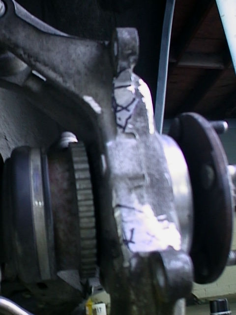
4. Install the Bracket onto the CaliperThe picture above also shows the bracket mounted to the caliper. Use the 7/16" bolts to connect them up. Use a flat washer on each side and a split lock washer under the nut. Torque the nuts to about 50 ft-lbs. Note that the other bolts in the picture (bracket to upright) were too long (60mm) so I used a bunch of washers until I could get some that were the right length. I don't recommend using a bunch of washers like this, and you won't need to if you get the right (M10 x 50mm) bolts. 5. Grind the Upright for Caliper ClearanceNow that you have a bracket/caliper assembly, you can use it for test fitting on the upright. You'll have to remove material from both the top and bottom of the upright this time, so you can't do the "bolt and swing" trick like you can with the bracket alone. You will have to remove more material from the bottom than from the top. Just keep test fitting to see what area you need to work on. I used a black Sharpie marker to mark the general area that needed attention during the test fits. Here is what mine looked like after I removed all the material to fit the caliper without any contact (both sides):
I took a little more off the top of the right side than I really needed to. Also note that the bolts in the mounting holes on the upright on the left are going the wrong way, as you won't be able to mount the caliper with them that way. The nut will actually be where the bolt heads are in that picture. 6. Install the RotorThe next step is to install the rotor onto the hub. I took a moment to clean some of the rust off the hub so the rotor would slide on more easily. Use some brake parts cleaner to wash the loosened junk away. 7. Install the Caliper AssemblyClean off the caliper and the upright with some brake parts cleaner. Slide the caliper over the rotor and into place on the upright. Use the M10 x 50mm bolts and slide them through the holes staring on the diff side. I would have liked to use a flat washer, but the bolts aren't long enough for that, so I did not use a washer under the bolt head. I did use flanged bolts with a smooth surface under the head, so the lack of a washer wasn't such a big deal. On the other end of the bolt, I used a flat washer, split lock washer, and a nut. It is a tight squeeze, but it should all fit in there without hitting the rotor once everything is tight. I torqued the bolts to 40 ft-lbs. Here is what it will look like with everything installed:
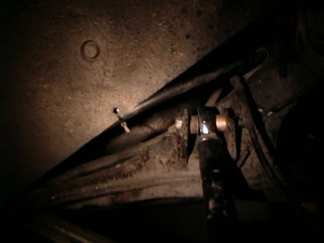
8. Install the Brake LineLoosely install the 90 degree fitting onto the fitting on the back of the caliper. Don't tighten it down yet. Use a flare nut wrench to remove the hard line from the stock brake line before removing the clip. Remove the clip. Pull the end of the new line up to the hard line. It won't fit into the mounting tab quite the same way the stock line did, so you'll need to use a wrench to keep the fitting from turning as you tighten the flare nut. Tighten the flare nut with a flare nut wrench. I reinstalled the clip, but it doesn't really hold the new line quite like it held the stock line, but it does seem tight enough that it won't fall off. Use a 1/2" wrench to tighten the 90 degree fitting at the caliper, being careful to orient the fitting to minimize contact with the suspension arm. My fittings ended up roughly straight down, though perhaps with the bottom pointed out toward the back of the car just slightly. You don't want them to stick out a lot or they might hit the wheel. I ended up with a little line contact on the suspension arm on one side. I should probably install some kind of sleeve to keep the braided line from scratching up the suspension arm, but you really can't tell how it will be until you drop the car to get the suspension in a "normal" position. Here is a picture of one of the lines installed: 9. Install the Brake PadsRemove the bridge bolt from the caliper. Slide the pads in. Reinstall and tighten the bridge bolt. 10. Bleed the BrakesThere will be a lot of air in the system after installing the new lines and calipers. Everyone has their own favorite bleeding technique, but be aware that Speedbleeders (my old favorite bleeding system) don't work very well with a large amount of air in the system. I got a Power Bleeder from Motive Products and it is fantastic. I don't think I'll ever use anything else. Be sure to bleed both sides of the caliper (use the top bleeder screw on each side of the caliper). You'll need a 1/4" open end wrench to open the bleeders. I didn't have one that small, so I used a 1/4" deep well socket and spilled a little fluid down the caliper that I later cleaned off with brake parts cleaner. 11. Secure or Remove the Parking Brake CableSince the parking brake cable will no longer be connected to the caliper, you must either remove it or just secure it somewhere to keep it from interfering with the suspension or bouncing around. I didn't feel like getting under the car too deeply, so I just secure mine. I pulled it forward toward the front traling link mount and used safety wire to hold the end there. I figured I would surely forget and pull the parking brake handle at some point (and I did, twice within 30 minutes of finishing the install), so I secured the end of the cable sleeve and let end of the cable hang free. I also drilled a 3/16" hole and used a cable tie to keep the cable from coming out and hitting the wheel or tire. The pictures below show how I secured the cable:
12. Go for a DrivePut the wheels back on and take the car off the jack stands. Torque the lug nuts. Do some low speed brake tests before you hit the road to be sure that you can stop. Go for a drive and be sure to follow the bedding procedure for your new pads. Once the pads are properly bedded, find a safe place to do some fast stops and see how it performs. It is generally bad if the rear wheels lock before the fronts, so it is probably a good time to test for this condition before you have to do a fast stop on the street or track. If the rears lock first, you can get an adjustable proportioning valve to replace the stock valve in front of the ABS unit. You might also be able to dial out the rear lock by lowering the car (less weight transfer during braking) or try a relatively lower friction pad compound in the rear. I still need to do some more testing, but I think the fronts still lock first on my car with Ferodo DS2500 pads front and rear. |
|
The information on this page is Copyright © 1999-2002 Max
Cooper |